Updated: 2020-09-03
I made a dance game pad out of plywood and load cells. It was cheap (125 USD) and worked pretty well. Scroll down to see how I did it!
About Dance Games
Dance Dance Revolution is the best video game ever. In this game, you listen to music and step your feet on specific buttons on the musical beat. It’s super fun, trains focus, stamina and dexterity, and is also an excellent way to do high intensity intermittent exercise, which is the Best way to exercise.
Usually you play DDR in video game arcades, but you can also play it at home with free open source software StepMania, songs downloaded from Zenius-I-Vanisher and a USB dance pad.
For starters you can get a basic pad for cheap (15 USD) but soon you crave precision and responsiveness and friction. Stronger foam pads (50 to 100 USD) do a little better. The best dance pads are made of thick, rigid material like metal and cost 300 (The Polish Pad) to 1300 USD (StepManiaX).
OR with a little bit of courage and effort you can make your very own legit dance pad for cheap: ~125 USD.
Below is my story of how I did it. To be honest, it’s a big-ish project, but it was really fun to dance on something I built! Check it out and if you have any questions, you can email me at ayumi @ ayumiyu.com.
Pad Design
Dance pads are simple. There are buttons – up, down, left, right – they are sensitive to pressure and send sensor data to a little computer which interprets it and sends corresponding keyboard events to the computer running DDR.
This dance pad uses strain gauge load cells as pressure sensors. The frame is built from plywood and is 2 pieces – base plate and button frame – sandwiching the 4 arrow buttons.


SVGs


Controller code
https://github.com/ayumi/ddr-pad
Materials
Frame / Non-electronic
- Base plate – Plywood, ACX, 4’ x 4’ x 0.5”. (Something nice to handle sweat and jumping humans)
- Buttons – Plywood, ACX, 4’ x 2’ x 0.5”.
- Button frame – Plywood, ACX, 4’ x 4’ x 0.75”. (Note thickness of 0.75”)
- Bolts – M5 1.5 x 25 mm, head <= 5 mm; 16 pieces.
- Threaded inserts – Hex flanged; size to bolts; 16 pieces. (Get a few extra) (TODO: Find precise size).
Electronic
- Sensors – Strain gauge load cells, 50kg; 16 pieces. AliExpress link.
Consider a few extra. also ePacket shipping is nice. - Sensor amplifiers – HX711; 4 pieces. Amazon link; cheaper from AliExpress. Consider a spare for debugging.
- Microcontroller – Maple mini, or anything with 4 analog input pins and 4 out pins. Consider a spare.
- Connectors for crimping sensors
- 3 pin connector; 4 pieces.
- Pins; 16 pieces.
- Connectors for amplifiers and microcontroller
- Right angle. (Helps with vertical clearance under buttons.)
- Jumper wires – To wire everything. Pin to pin; 100 pieces.
- Electrical tape – Useful.
Cost estimate
- Plywood: $65
- Bolts: $10
- Bolt holes: $10
- Load cells: $20
- Amplifiers: $5
- Microcontroller: $5
- Connectors: $10
Total: $125
Tools
NOTE: You need a way to cut plywood at precise depths. I used a Shaper Origin which is a CNC router that cuts according to SVGs.
- CNC router – Shaper Origin. Precisely cut plywood.
- Computer to run apps:
- Power drill and bits
- Impact driver
- Hex wrenches
- Clamps – Hold plywood in place and absorb tool vibrations.
- Sandpaper
- Wire stripper – Crimp load cell connectors.
- Wire crimper
- Soldering iron and solder
- Breadboard – Debugging.
Procedure
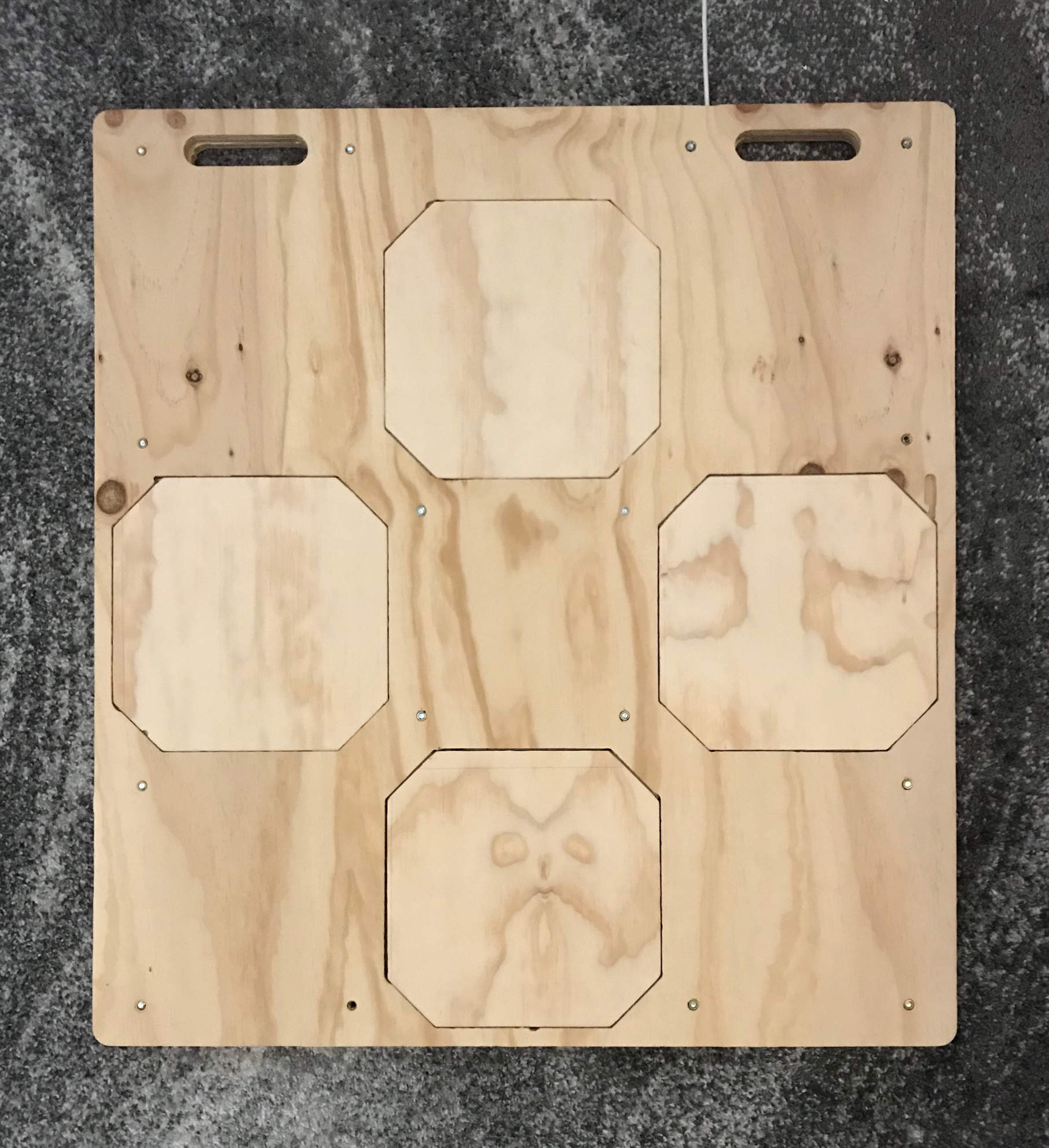
Button frame (back)
First I cut the button frame from the half sheet of thick (0.75”) plywood. Note we’re cutting with the back side face upwards. This is important because we first want to cut button slots from the bottom.
1. Border
Cut the outer border of the button frame. NOTE make sure you cut along the outside of the border, so your cutting device doesn’t eat into the actual dance pad. You want to leave the border nice and thick for strength.
Cut the two carrying handle holes.
2. Electronics place
The top right has a large pocket for electronics like the microcontroller and signal amplifiers. Cut this at depth 0.4” into the bottom of the button frame.
There’s a long rectangle extending from the electronics pocket up and out. This is the USB cable slot. Cut it at depth 0.2”.
3. Button slots
Each button has 4 corners, each of which is cut at depth 0.4” and offset -0.04” inside (slightly further into the frame than on the SVG) into the bottom of the button frame. See above Proof of Concept pic for reference.
Cut the 16 button corners at this partial depth.
Then cut the 4 button inner octagons at full depth (0.75”) and also with offset -0.05” inside. These pop out. You don’t need them but you can save them for future projects.
4. Threaded insert holes
In the SVG each hole has 3 circles. From small to large: Bolt (-> Base plate), Threaded insert (-> Button frame) and Bolt head recess (-> Base plate bottom). For the button frame plywood we’ll cut only the middle circle (threaded insert).
Cut the 16 threaded inesrt holes at full depth.
Base plate (front)
The base plate holds the electronics. It’s cut from the half sheet of medium thick (0.5”) plywood.
We’ll cut most of the features, then flip it over to cut the recessed bolt holes.
1. Border
Cut the outer border, making sure to cut along the outside of the border to preserve the area of the dance pad for strength.
Cut the two carrying handle holes.
2. Electronics spaces
Cut the top right electronics pocket at shallow depth 0.125”. Cut the top right long USB hole to the same shallow depth 0.125”.
The buttons have channels for sensor wires leading them out and toward the electronics spaces. Cut the button sensor wire channels at the shallow depth 0.125”. (TODO: If sensor amplifiers need to live in these channels, you might need to cut out a slightly bigger/deeper space for them.)
3. Load cell slots
There are 16 slots for load cells. For each one you need to make 2 cuts:
The main body of the shape at depth TODO and The bigger circleat depth TODO. (The little circle you can ignore. it fits a bump on the load cells)
Base plate (back)
Flip the base plate over to cut the bolt holes.
1. Bolt holes
First cut the outer circles as deep as needed to fit the bolt heads. Then cut the inner circles fully for the bolts.
Buttons
Use the quarter sheet of 0.5” thick plywood.
1. Cut
Each button has 4 corners, each of which is cut at depth 0.235”. (Note there’s no inner offset here.) Cut the 16 button corners at this partial depth.
Then cut the 4 button squares out at full depth (0.5”).
2. Fit
Test these by fitting them into the button frame. You are aiming for a snug but slightly wiggly fit. You might need to trim the buttons.
There might be an optimal way to fit your 4 buttons into the 4 slots. After you determine that, label the backs so you remember it.
Pre-assemble
Fit everything together. The trickiest parts are button fit and bolts.
For bolts, work on a single one first. On the button frame insert the threaded insert with flange facing down. Then turn it over, put the base plate on and screw the bolt in from the bottom using the impact driver. Adjust holes as needed.
Once done, screw in all the threaded inserts then check you’re able to start screwing bolts into every hole. (In my case, I had to widen most bolt and bolt head holes).
Electronics
I found this part the most difficult, as there are many many wires to connect precisely. Make sure to secure all connectors.
1. Connectify load cells
Load cells have 3 wires and they’re usually bare. Crimp the wires and add to 3-pin connectors to make them easier to work with.
2. Connectify electronics
Solder connectors onto microcontroller and amplifiers.
3. Adjust signal amplifiers to 80 Hz
The HX711 reports signals at 10 Hz stock but can be adjusted to 80 Hz with some semi tricky soldering:
bend pin 15 away from the pcb [8] and then link to pin 16
This step is optional; however I recommend you do this, as the DDR Marvelous judgment window is 10-15 ms and you want to hit Marvelous :)
4. Test electronics
Prepare your computer with the Arduino software and needed libraries:
- https://github.com/bogde/HX711
- USB HID
Download the (TODO) [HX711 test program for Arduino] then flash it to your microcontroller. We’ll use this to test everything.
Prepare this 2 load cell test circuit on a breadboard. Connect the load cells to the amplifier, and amplifier power, ground, output and clock pins to the microcontroller.
Connect the microcontroller to your computer and view the serial output. It should show sensor values, and when you press on the load cells the values should changeuntil you let go.
Test all the amplifiers.
Test all the load cells.
5. Wire stuff
The circuit you’ll use is 4 load cells connected to an amplifier. Each amplifier has power, ground, output and clock pins connected to the microcontroller just like in the test circuit.
So you’ll need 4 sets of the 4 load cells -> amplifier; and 4 sets of amplifier -> microcontroller.
You should be able to fit wires and amplifiers under the buttons and in the base plate channels, but be extra sure that the button won’t crush them by periodically placing the button on top and examining from the side.
First wire up the 4 sets of 4 load cells -> amplifiers. Secure the 4 connected load cells then hook the amplifier to your microcontroller and test it. Each 4 load cells should change the output.
Then wire the amplifiers to the microcontroller. Upload the (TODO) [DDR dance pad program] to your microcontroller and test it. If you press the pad buttons there should be corresponding keypresses sent to the computer.
Finish
Assemble the pad. Download Stepmania, connect the pad and try to play a song. You might need to adjust audio offset (I have it set to -0.036 s).
Troubleshooting
The issues I’ve had thus far are all electronic. General debug process:
- A pad fails
- Connect to dev computer and view serial debug output
- Open it up
- Inspect/resecure connections and test again
- Use 2 cell test circuit on load cells and amplifier
Below are specific issues I encountered.
Pad works sometimes. If you hit it hard it starts working for a little bit.
Problem: Load cell has poorly crimped connector.
Solution: Detach connector and redo it.
Pad doesn’t work at all. Serial debug shows unchanging 0.00 signal.
Problem: Load cell broken
Solution: Swap out the load cell.
Pad gets stuck. Serial debug shows signal sticking to high values.
Problem: On two load cells, the connection between white/green wires is loose.
Solution: Resecure connection.
License
Changelog
- 2018-05-20: Created
- 2020-09-03: Cleanup, add pad links